


NATOPS1
-
Posts
785 -
Joined
-
Last visited
-
Days Won
7
Content Type
Profiles
Forums
Store
Gallery
Downloads
Calendar
C-130 Hercules News
Posts posted by NATOPS1
-
-
On 8/30/2023 at 11:49 AM, tinyclark said:
Still hard to troubleshoot with an unknown system.
What tiny said...
-
AD gates but the are rated at 5000 like all the non floor mounted rings.
-
That is exactly what you are testing but also during test you "simulate" the wheels rotating (lights out) and the system control box should "release the brakes" (lights come on)
-
Some non operator somewhere calculated the flow rate and figured it was long enough based on the size of the pipes... But FWIW based on the pump rated output and the size of the pipe as well as the distance needed to travel one could (or has) figure out how much time is needed.
-
Closed keeps cold air out and prevents cold soaking the oil inside the cooler.
-
 1
1
-
 1
1
-
-
Have your crew try ATL SELECT and then ALT HOLD
Two different sources for the ALT function
-
On 6/3/2023 at 7:33 AM, HerkyFE said:
So is the callout 'valve' referring to releasing the starter switch?
Thanks!
The valve (closed) call is for the starter control valve not specifically the switch release. "starter" is the call to release the start switch. When the valve closes on engine 3 the APU bleed air will increase which is the trigger for the valve (closed) call. On second third and fourth engine start TIT decrease is the indication used to trigger the valve (closed) call unless APU air is used.
-
Allows enough fuel to flow through the manifold to remove (push) any air "Priming" means removing the air.
-
As you rotate the selector you switch the wire contacts so a momentary drop is not a problem because you are not connected to a phase input until you get to the next phase position. You select not only the phase for your freq indicator but also the phase for your load meter.
-
The wheels will spin after takeoff until they loose rotational energy and stop on their own. There is no "brake" action to stop them.
-
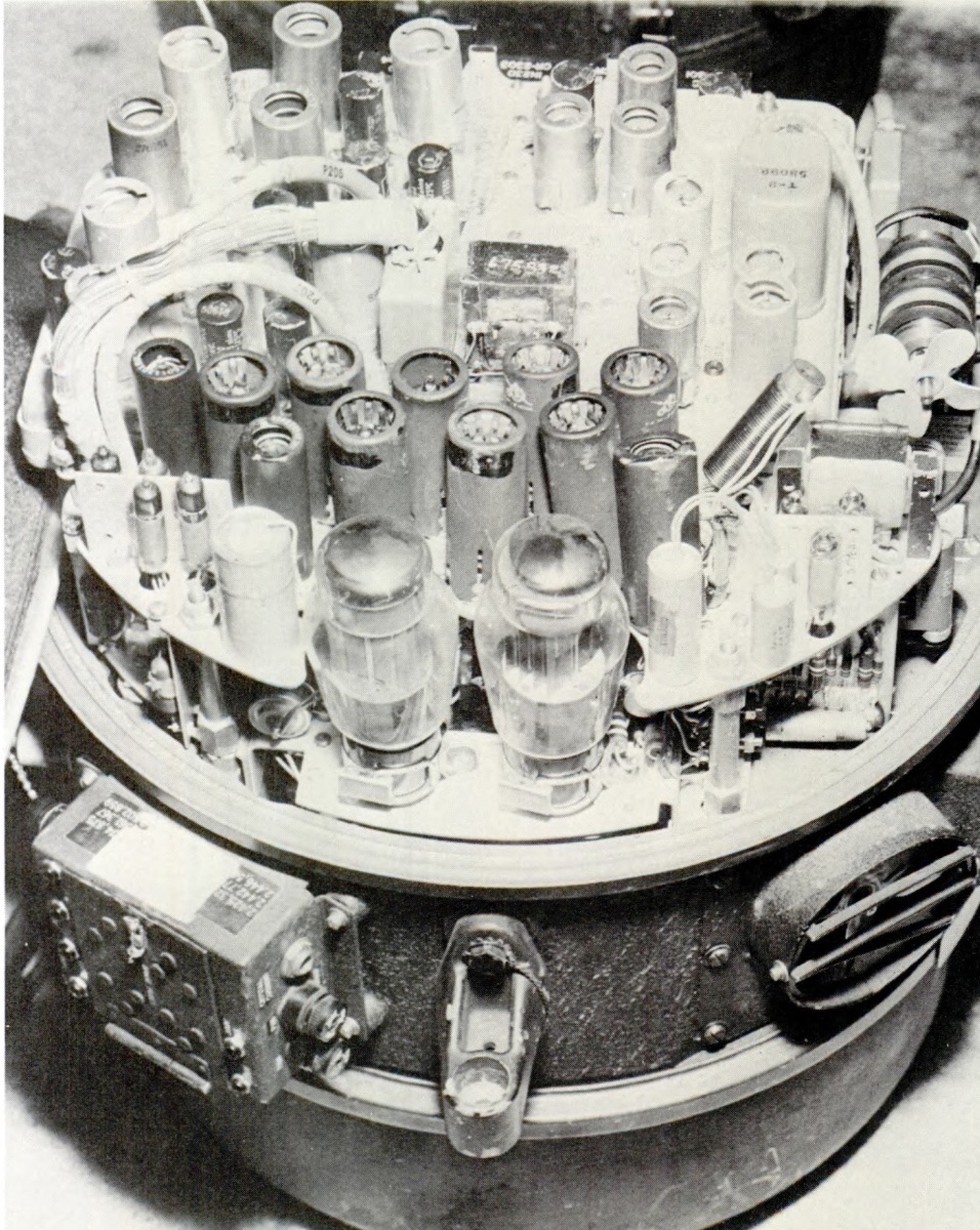
On 6/11/2021 at 6:27 AM, Robert Podboy said:
What early C-130 systems had vacuum tubes?

Nice APN-59 Barrel!! Replacing that freekin thing SUKED!!! Replacing the cannonplug SUKED MORE!!!!
-
A few questions to narrow the task:
What model aircraft?
Inop as in:
(a) never turns ON stays cold (watch the pressurization system climb/descent gauge)
(b) gets HOT then turns off
(c) other manifestation?
-
What ICS system do you have? The following info is for the AIC-14 system...
Change the P and CP AMP selected from Norm to Alt 1 or Alt 2
Also inside the ICS and Radio select boxes there is a jumper to "change the function of the box (same box two functions) make sure the jumper it tight (remove clean contacts and reinsert jumper)
If there is a problem with the ICS the boxes will change to a sort of "Hot Mic" function connecting the P and CP ICS
-
From what I remember the difference in location changes the airflow around/through the boundary layer and it is more of a pickup /interpretation difference but if you are so inclined you can go through the performance charts and determine it there is a TAS difference.
-
Too many to list... obvious difference, 4 tubes in the Rosemount vs only 2 in the non. The systems the tubes attach to are all different.
FYI, ONE VERY IMPORTANT aspect is the performance charts are different for the two systems; if you use the wrong chart for calculating your TOLD data you will have incorrect numbers.
-
Sounds like a bad GCP: internal (PIR) or internal TR... Make sure your GCP is the same manufacture as your generator; ALSO make sure the GCP is fully seated in the rack and might want to "adjust it" with a quick hit/rap/ wack to get all the connections to make good contact. SWAP with one of your Eng Gen CGPs to be sure.
-
On 4/13/2021 at 7:09 PM, Wheto Joseph Seyon said:
This particular sbag has been disturbing the team for the oast few weeks. What could be the cause, we have replaced the control unit, antenna and also TR unit. Checked every component in the system for serviceability but it still persists.
NOT a lot of info tto work with but IF the ground returns are only on one side of the display your ANT gyro stabilization is probably bad
-
1
-
-
23 hours ago, munirabbasi said:
Excellent JPG Picture of GEN DISC SYSTEM SCHEMATIC
Besr Regards
Munir Abbasu
You may need to have FLASH available for these animations to work (I think)
-
18 hours ago, Farhanz said:
will the T plunger will broken once initiated sir? i meant, the hardened steel plunger was found released. however, i did not know where is the exact location of the fusible plug mentioned in my manual. how is it melt and how is it released the plunger by melting the fusible plug??
The "fusible" plug (link) is the part that holds the spring compressed and the hardened plunger retracted. The test circuit is a lower amperage (7.5A if I remember correctly) and the disconnect power is 20 or 25A.
IF you hold the test "too long" you an heat up the fusible link and release the disconnect plunger gendiscon.bmp
-
On 2/26/2021 at 8:39 PM, Rzouga said:
Hello Herky people,
I want to know how to use exterior lightning on the ground (day/night),in flight(day/night) depending on weather condition.
thanks
Read the FARs or ICAO for your situation
-
On 2/24/2021 at 2:53 PM, smain said:
What is the role of fuel vent check valve ?
You need to be more specific.
Which part of the fuel system are you asking about?
-
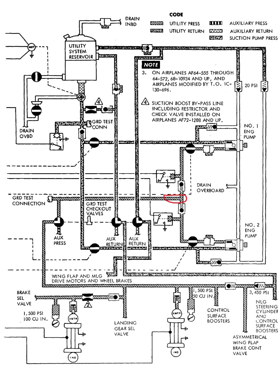
On 12/17/2020 at 8:40 AM, munirabbasi said:
Hello Herks Hydra Expertise!
1. It has mentioned Intermediate level maintenance T.O of EDP NYAB at 3000 RPM , flow rate of pump is 6 GPM min, where pump is designed 10 GPM at 3650 RPM . when both the pumps (NYAB) In Aircraft utility system working parallel max flow ie 16.93 pressure drop to 1800 psi. how we can calculate flow rate (GPM) of both NYAB pumps when they are working parallel at 3000 RPM?
2 Just assume that aircraft hydraulic utility system ,when No 1 EDP pressure is 3000 psi and No.2 EDP pump pressure 3100 psi how the pressure act passes thru passage of single pipe after isolation check valves ?
Best Regrads
Munir Abbasi
Home Hercules Pakistan
Question #1: No idea on GPM @ 3000 rpm between 6 and 12 is all I got on that...
Question #2: Just assume that aircraft hydraulic utility system ,when No 1 EDP pressure is 3000 psi and No.2 EDP pump pressure 3100 psi how the pressure act passes thru passage of single pipe after isolation check valves ?
The 3000 PSI pump will be at zero flow because the pump compensator (set at 3000) is satisfied with the pressure. The isolation check valve for this pump will be closed due to the 3100PSI being applied to the check valve preventing it from opening.
The 3100 PSI output pump (compensator is set incorrectly) will displace fluid to maintain 3100 PSI, it's isolation check valve will be open and the system pressure gauges will read 3100.
As hydraulics are used the pressure will drop and the 3000 PSI pump will be allowed to help out but only until the 3100 PSI pump builds its pressure back to 3100, then the 3000 pump will again go to zero flow condition.
-
ALSO FYI; The flight station mounted bleed air gauge reads 6 PSI lower than actual pressure. Add 6 to the indicated pressure for actual pressure being supplied.
-
The orange boot is covering the connection to the main bleed air duct. Would need your model AC to get the actual part we are looking at.
Bob Daley Passing
in C-130 Community Announcements & Promotions
Posted
Bob shared so much knowledge and experience that he is still out there flying in the brains and hearts of the aviators and maintainers he helped learn, fix and fly their Hercs. Be like Bob; what you have been taught, learned and experienced will only last forever if you teach and share your knowledge and experiences with our fellow aviators.
Rest easy brother...
Godspeed