


victorp1
-
Posts
53 -
Joined
-
Last visited
-
Days Won
1
Content Type
Profiles
Forums
Store
Gallery
Downloads
Calendar
C-130 Hercules News
Posts posted by victorp1
-
-
When I flew on the C-121J we closed the cowl flaps and oil cooler flap to reduce drag.
-
 1
1
-
-
Using a Flow vs Pressure chart, at 24 PSI flow thru the primer valve should be approximately 7 US gallons in 30 seconds.
-
EPC 2192 - Change released to T56-A-15 engine, TD Amplifier P/N 23059687 changed to P/N 23089510
-
Have you selected Emergency Brakes after gear is up then apply brakes to stop wheel rotation, if you desire? We normally did not apply brakes in flight to stop wheel rotation because we did not want the tire to slip on the wheel.
-
Here is some information from years past.
HERCULES Service Information Letter
A SERVICE PUBLICATION OF LOCKHEED-GEORGIA COMPANY, A DIVISION OF LOCKHEED CORPORATION
Dated 1 AUG 1978, Issue Number 27
HYDRAULIC FLUID INTERCHANGE BETWEEN SYSTEMS
Due to certain malfunctions or incorrect procedures, hydraulic fluid may interchange between systems causing one system to be low and the other to possibly overflow.
Ground Test Interconnect Valve
Occasionally the ground test interconnect valve is suspected bad and changed when it is not malfunctioning. All ground crews must remember that: ALL UTILITY ANO AUXII.IARY HYDRAULIC SYSTEMS PRESSURES, INCLUDING NORMAL AND EMERGENCY BRAKES, MUST BE ZERO PRIOR TO SHIFTING THE GROUND TEST INTERCONNECT VALVE HANDLE.
It is imperative that the following precautionary steps be strictly adhered to prior to shifting the ground test interconnect valve handle in either direction:
1. System hydraulic pressure must read zero on all utility and auxiliary system gages, and all accumulator air pressure gages must read pre-charge pressure only. (Utility system pressure can be depleted by cycling the controls. Auxiliary system pressure can be depleted by cycling the aft cargo door.)
2. Actuate the normal and emergency brakes until pressure on both cockpit gages is zero.
If the utility system is pressurized while the ground test valve is in the normal position, approximately 50 cubic inches of fluid will be pumped from the utility reservoir to the normal brake accumulator. If the utility pumps are then shut off, the fluid will remain trapped in the brake accumulator. Assuming then that the ground test interconnect valve is switched, if the brakes are actuated several times, the 50 cubic inches of fluid which came from the utility reservoir will return to the auxiliary reservoir. If the ground test interconnect valve is then positioned to normal, the transfer of the fluid from the utility system to the auxiliary system will be complete.
Accumulator
The utility system and normal brake accumulators can cause a fluid interchange if leaking air across the piston. With the interconnect valve in NORMAL position, air leaking from these accumulators will seep into the utility return line and displace fluid which wi11 return to and eventually overfill the utility reservoir.
The actual transfer of fluid occurs when the utility system is pressurized with the auxiliary pump. Fluid pumped from the auxiliary reservoir goes to fill the partially empty utility system lines; if the interconnect valve is then repositioned to NORMAL, the fluid is lost from the auxiliary system and added to the utility system. The transfer may occur in the opposite direction (from utility system to auxiliary system) depending on the positioning of the interconnect valve and operation of the system.
Other Causes
If fluid is still being interchanged between the utility and auxiliary systems, the following components should be checked for internal leakage:
o Nose landing gear shuttle valve.
o Four main brake shuttle valves.
o Two brake metering valves.
o Nose landing gear uplock cylinder.
-
1
-
-
Each wing had three formation lights and the early "B" had fuel filler ports for over the servicing. After the first center wing modification the filler ports were removed and a oval center wing hatch was installed to replace the square one. The square dry bay hatches were replace with oval with a outer wing upgrade.
-
I flew a C-130 which kept having prop fluid disappear with no external leakage. The prop fluid was going to the engine oil system due to the O-ring on the plug in the propeller shaft. We replaced the O-ring and life was good again.
Vic
-
n1dp,
That sounds like the L-382E/G or L-100-30 aircraft. The light will extinguish when the cabin altitude decreases to approximately 8,000 feet. I am not sure what C-130H or C-130E has this modification in their aircraft.
Vic
-
From an old Allison Service Information Letter it states"
"Reason:
The purpose of this SIL is to define:
1) LFE "Lockheed Furnished Equipment" designated T56 engine models.
2) Allison policy regarding administration and logistic support of LFE engines.
D. Description:
Engines with the LFE suffix are built to military engine model specification and are sold commercially as opposed to a U.S. Government contractually built engine sold to the U.S. Military (without the LFE suffix). They include all engineering changes as their military counterpart from production and have technical directives complied with that may not have been accepted by the U.S Military
Technical Directives
T56 LFE engines are not civil certificated by the FAA, however Allison sells them under a commercial maintenance plan and warranty program. Allison includes the LFE engines in our Service Information Letters, Commercial Service Letters, Commercial Engine Bulletins, and Commercial Overhaul Information Letters in order to provide LFE operators with information and product improvement modifications that are designed to improve durability, extend overhaul times and increase reliability."Vic
-
I asked the same question 1999 when it was put into a customersFlight Manuals and this is what I got back:
"An analysis was conducted to verify the rigid and flexible pavement ACN charts and to review the assumptions used in chart development.
The runway strength requirement ACN charts published in the C-130J Flight Manuals are being recommended for inclusion in all flight manuals. These charts are constructed in accordance with International Civil Aviation Organization (ICAO) recommendations, and are based upon a constant tire pressure which corresponds to 32% tire deflection at maximum, normal operating weight. This data is applicable to both standard and stretched models of the C-130 and should result in successful operations on runways having PCN values equal to or greater than the ACN values contained in the flight manual charts.
Any deviations from tire operating pressures corresponding to the 32% tire deflection criteria, or flotation capability evaluations by alternate methods (i.e. LCN, LCN/LCG, or CBR), must be considered on a case by case basis."
Vic
-
If you swap the indicator to a different position can the indicator be adjusted for the new position?
-
On the EPCS the backup solenoid is energized by the throttle position, lifting it up to come into the ground (beta) range. This is not normally tied into the touchdown electrical system. If the throttle cable breaks and takes the engine/propeller linkage to the reverse position the backup solenoid will not allow the blade angle to decrease below low pitch stop position as long as the throttle remains in the flight (alpha) range.
Vic
-
If it is an outboard engine and the temperature controlling check is completed according published procedures and it only happens when wings are flexed (loaded) during flight you may need to look at the electrical connection at the wing break.
-
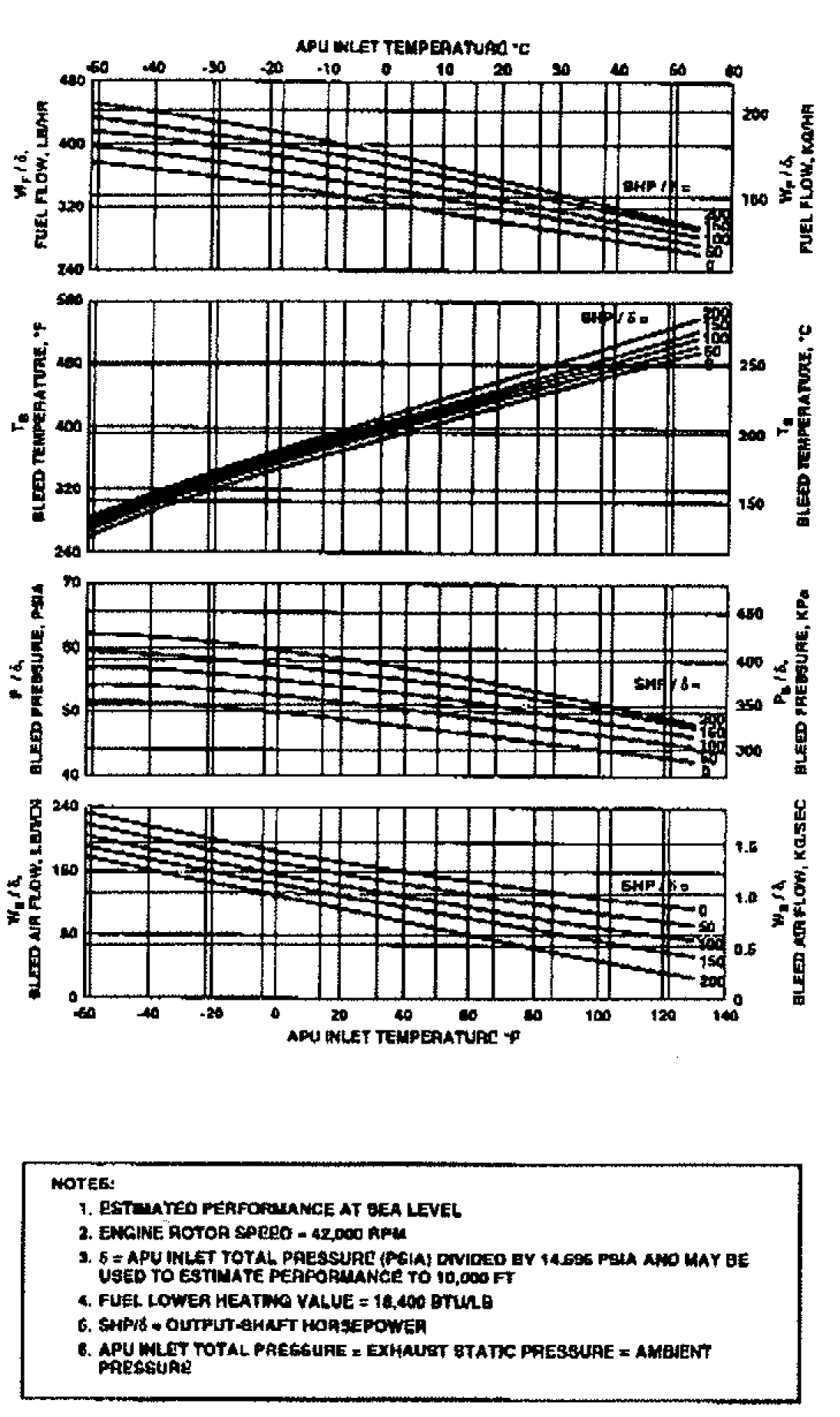
This is a portion of the Specification Data for Model Garrett 850185[L] APU.

-
I would recommend contacting Kellstrom Defense Aerospace, Inc., 3701 Flamingo Road, Miramar, FL 33027, Phone Number 954-538-2000. They have sold installation kits to some of the customers who come to CAE Tampa Training Center for initial and refresher training. They seem to be happy with the kit installation.
One point of contact I have for Kellstrom is Terry Gray, [email protected].
Good Luck
-
Has anyone marked on the casing with a lead (Pb) pencil? This normally causes a burn through on hot section metal.
-
NATOPS,
In the Flight Manuals I have looked at all have "ATTAIN A SPEED" in them. I also looked at an old handout I got at a Hercules Safety Team Brief about 30 years ago and it has some helpful information about decouple, showing RPM with specific blade angles.
150 KIAS is the best range for decouple with lower blade angles, approximately 23° to 36°, and to keep the RPM from being too excessive when the engine is shut down.
The worst case mentioned is when decouple occurs at 23° blade angle. At this blade angle if KTAS is 190 the RPM would be approximately 170% and if KTAS is 150 RPM would be approximately 135%.
At cruise blade angle, approximately 50°, RPM would not be a factor. At 200 KTAS the RPM for both coupled and decoupled is approximately 60%.
I hope this helps.
Vic
-
When you talk about H1, H2, H3 and so on you need to be a little specific about what operator you are talking about.
In Sweden they have what they call H1 and H2 aircraft, Algeria has a verity of H models from H1 through H6. Many other operators around the world use this identification method also which has nothing to do with the USAF call their H series aircraft.
I normally find it easier to identify aircraft by the Lockheed serial number and then find out what the operator modifications are to aid in describing the differences.
Vic
-
The Lockheed Baseline FM 382C, Section 5 (Nonstandard Operations), has a procedure named "ENGINE STARTING WITHOUT AC ELECTRICAL POWER". This may help.
Vic
-
With revision 26 to the AFM the L-382 is authorized to operate with servo gov valve housings on the outboard positions.
-
If the OAT is very low and any moister in the fuel filter/strainer it will freeze and not allow fuel to flow properly. I have had this problem but once we were on the ground, even with ground OAT of 0°C, the fuel will flow and start properly. I had this problem on GTC's also, it would not start right after landing but after about 15 minutes it would start and run properly.
-
It may be due to brush type generators. Years ago we had brush type generator and the brushes had to be inspected/replaced on specific intervals, similar to an ATM generator. When brush type generator were installed we were limited to 0.625 load while on the ground.
Vic
-
It may be due to brush type generators. Years ago we had brush type generator and the brushes had to be inspected/replaced on specific intervals, similar to an ATM generator. When brush type generator were installed we were limited to 0.625 load while on the ground.
Vic
-
Tiny,
You are correct that is to allow the excess air to escape when wing anti-icing is used. Some individuals think the relief hole on the outboard section of the leading edges are the only relief.
Vic
Is it possible to retain Flight Engineer (FE) and Navigator (NAV) positions in a modified C-130H with an updated Flight Management System (FMS)?
in C-130 Technical
Posted
We have the Rockwell-Collins Flight 2 equipment in one of our simulators. We have been training with multiple customers who operate this system in their C-130 aircraft for about the last five years. The operators who had navigators kept them. All the operators have flight engineers.