

pjvr99
-
Posts
584 -
Joined
-
Last visited
-
Days Won
10
Content Type
Profiles
Forums
Store
Gallery
Downloads
Calendar
C-130 Hercules News
Posts posted by pjvr99
-
-
i havent used the balancer yet so cant answer your question directly. however, a couple years ago we got a
newly overhauled prop in the test cell. Everything was fine up to NGI. As throttle was advanced and blade angle
increased, the prop noise and RGB vibration increased. Above 1000° TIT the noise was like someone or
something beating on your chest - unpleasant, almost painful. RGB vibration was topping at 1.4 to 1.6 mils.
We went through the prop records and everything seemed to be in order. We then did a loose blade and
tracking check, which also checked good. While standing a distance away from the engine looking at
the prop, we thought there was an optical illusion. It seemed that the #2 and #4 blades were narrower
than #1 and #3. On measuring the width at various points from the tip to +- halfway in, we found the #2
and #4 blades around 2 inches narrower than the others.
These 2 blades had a couple thousand hours on and had been reworked several times, while the other 2 were
new. Essentially there were 2 blades working their asses off, and 2 just along for the ride. My thoughts are
the noise and vibration were being generated by the 2 working blades being at a higher than efficient
angle and probably very close to stalling.
Just something to think about .....
-
WOW! System wide failure .... did you get it figured out? We've had a lot of wierd stuff with
our EPCS birds, but this one is a first.
-
What aircraft model?
-
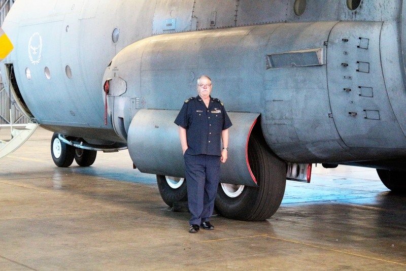
Warrent Officer, South African Air Force,Henk van Rooyen with 12000 hours on C130 (Herc's) and a career spanning 43 years active
duty has finally come to an end. Henk from all the squadron members, Goodbye and good luck.
(Picture taken from facebook group)

-
First thought would be low pitch stop is not set correctly, however more info is required. What
was airspeed, altitude and throttle position? Same for other engines and their indicated torque?
-
I've been down this road before - the numbers his fleet manager is insisting they use are not correct. My test cell has
digital and analogue torque indication. The digital easily spans numbers like that, the analogue guages cannot. I was
proven right when my boss had one of the tm i failed sent to RollsRoyce for evauation. Report came back with 7
defects including excessive twist (overtorque) of the torque shaft. The tm unit had been overhauled by another
facility
-
all i can say at this point is the numbers you are trying to use are wrong. follow your job guide or tech orders for doing tm
calibration, NOT the numbers given to you
-
On 11/17/2017 at 12:56 PM, ermitao said:
This engine in question came from overhaul as well the torquemeter, the value from backshop is 29540, and they said to put on cal A -2340 and on cal B- 27200. ...........
So what do you think about these values?
If torquemeter stamped number is 29540 then corrected cal-A of -4000 would give corrected cal-B of 25540. Assuming ISA conditions
and 72% rpm, you would be looking at 709"lb torque calculated. Setup indicator as per 1C-130H-2-77JG-00-1 77-10-04. A difference
of more the 50"lb will require corresponding adjustment of the guage. A difference of 750"lb requires tm remove from service. Try my
min torq calculator if I am not clear .....
-
no minimum value stamped on tm. T.O. says unload engine by turning off bleed air, generator and hydraulic pump. Then move
throttle slightly forwards or backwards to obtain LOWEST torque indication. Adjust CAL-A/CAL-B -4000/25850. If the difference
between INDICATED torque and CALCULATED torque is more than 750"lb reject torquemeter and return it to overhaul.
-
However I did find this .....
-
.... I'm going blind ....
-
APN = Aircraft Production Number? If so, its on the data plate above the flight engineer station
-
Hey guys
Got a list of positions open with SAEI (Saudi Aerospace Engineering Industries). If anyone is interested
send your Cv and certificates to my email: pjvr99@gmail.com I don't have salaries, they can be discussed
during interview
# Slot No. Job title 1 w-1 PMEL SPECIALIST 2 w-2 PMEL SPECIALIST 3 W-29 JET ENGINE & PROPELLER SUPERVISOR 4 w-31 QUALITY CONTROL SUPERVISOR 5 w-33 Flight LINE Maintenance Supervisor 6 W-52 AIRCRAFT MAINTENANCE TECH. 7 W-53 SUPPLY ANALISYS SYSTEM 8 W-55 OPERATIONS SPECIALIST 9 W-89 PERIODIC INSPECTION SPECILSIT 10 W-91 FLIGHT LINE SUPERVISOR 11 W-107 CURRICULUM SPECIALIST Thanx
PJ
-
Sounds like a bad speed valve ..... when you change the valve, take a good
look at the drive socket in the ADH for excessive wear
..... another culprit could be the scoop anti icing valve - they have
a tendency to pop open at high power settings when they get
older
-
The engines have 2 speed settings, low speed ground idle and normal. Low
speed is used to start and stabilize the engine, and also to do minimum
torque calibration. Engines are generally held in low speed for taxi as it is
easier to control oil temperature, than in normal. The #3 engine is
sped up to normal to provide extra bleed for a quicker start on the other
engines, and to provide air for the air conditioning packs. The APU
provides +-40psi air pressure (unloaded) while an engine provides 80
to 100psi, although this is regulated to 70psi on some
models
Also use of low speed reduces fatigue on turbine assemblies
-
There is nothing in the engine or RGB that can cause a pitchlock condition. However, I'm wondering whether crew is
giving correct debrief. You mentioned problem occurs during descent. If the NTS clearance is tight and pilots
throttle back too far too quickly, they may be engaging NTS system momentarily - query the crew on that.
-
How is the in flight check being Performed? What steps? What is or is not happening?
-
Please confirm that the following parts were NOT transfered from
one propeller to the next when the propellers were changed:
valve housing
pump housing
PITCHLOCK regulator
brass barrel nut
Thing that sticks in my mind is the PITCHLOCK system is essentially
mechanical, meaning once a COMPLETELY different propeller is
installed the problem should go away. I wonder if the problem being
experienced isn't maybe an engine roll-back .... this is just a thought
-
For the GTCP85-180 series we used T.O. 2G-GTCP85-41-1 ...... I don't know what the commercial equivalent is
-
Synchro operation can appear normal, but still cause trouble, which is
why I suggest running the sync tester. You mentioned that mechanical
governing has no effect - does that mean the crew put the prop to
mechanical before landing and it still pitch locked?
-
When you say "3 propeller assembly changed" does that mean 3 different pump
and valve housing? If so, you will want to run your sync tester - sounds like a
synchrophaser or sync rack problem, or a wiring problem in main control
conduit. Bearing in mind PITCHLOCK can only occur with low fluid level or
overspeed conditions
-
Ah! Sounds like fun.
-
What are you doing with it .... ?
-
Finally found the correct info:
Legacy C130E/H APU model is GTCP85-180L, PNo 381116-1- 3/5/6/7/8/9
C130 APU upgrade model no GTCP85-180LE, PNo 381116-3
L382 model no GTCP85-185L, PNo 381252-1-2
SMP1522
in C-130 Technical
Posted
Hey guys
Looking for a book in digital format: SMP1522
Is there anyone can assist me with this?
Tnx
PJ