


NATOPS1
-
Posts
785 -
Joined
-
Last visited
-
Days Won
7
Content Type
Profiles
Forums
Store
Gallery
Downloads
Calendar
C-130 Hercules News
Posts posted by NATOPS1
-
-
Check the fire loop element for stand off clearances from all ducts and foil covers. Make sure all the "clamps" are fully insulated from the fire loop as the element can "slip" through the split in the insulation sleeve.
Good luck...
APU fire light illuminate with both cargo and flight station AC systems?
Have you "motored" an engine with the condition lever in ground stop so it will not start?
-
On 11/21/2020 at 8:53 AM, munirabbasi said:
Hello World Hercules Fuel & Avionic Expertise!
All 14 fuel tanks electrical pumps are operated by 3 phase power supply , controlled through 3 phase (4 poles) SWs mounted on OH Fuel control & management panel, where others Aircraft, AC pumps are controlled remotely by single wire (single pole) SWs through 3 phase relays. what is reason behind it?
Best Regards
Munir Abbasi
Home of Hercules Pakistan
The pumps are connected to multiple power sources (and wire routing) so one set of wires accomplishes a simple control input to the pump regardless of power source.
-
On 11/26/2020 at 11:06 AM, Taimoor said:
On approach for landing, a C130 E Model aircraft lowers landing gears only. Flaps are already down. While Lowering the landing gears, utility pressure drops to 1375 PSI and low pressure EDP light of both Engines and low pressure light of Utility Suction Boost Pump illuminated. As soon as the Landing Gears were extended completely, system pressure came back to Normal with all conditions within limit. To what component can this occurrence be attributed? Can it be the failure of Utility System Accumulator, Suction Boost Pump or EDP? And if we were to attribute this to Accumulator, is it possible for an Accumulator to suck hydraulic pressure from pressure line to fulfill its pre charge pressure once it is used?
Change your flexible hydraulic line between the reservoir and the Utility Suction Boost Pump(USBP). IF the line collapses to a degree there will be less hyd fluid (gallons per min) available to pump through the USBP out to the EDP. High demand requires hi volume flow and the only place to restrict hyd fluid affecting both USBP and EDP is the flex line between the reservoir and USBP.
-
4 hours ago, hehe said:
Looks like a prison mirror that somebody put there. Definitely not standard on all C-130.
 Might be a "quick access" panel someone made to get to the ext power/ freq sense relays. Think that is the right panel... SHOULD BE a BIG RED WARNING sticker there toooooo
-
 1
1
-
-
There are multiple references to touch and go operations with fuel in the external tanks. Check your Normal procedures section for guidance.
Some places it says to land "with little, if any, usable fuel in the external tanks" and other places it says "Crossfeed from... external tanks may be done during… touch and go landings"
Not really a yes it is OK or a NO it is NOT OK, to do touch and goes with external tank fuel and crossfeed operations but your sink rate is limited to 300 FPM at touchdown any time there is more than 500LBS in the external tank. Less than 500 LBS is considered empty and the tank should not be used for crossfeed as pressure will probably not be maintained as the fuel level is too low to maintain pump pick up with the changing pitch angles.
Do you have fuselage tanks installed? If so you cannot have usable fuel in the external tanks with the fuselage tank not full (20,000LBS+)
-
1
-
-
On 4/22/2020 at 4:53 PM, casey said:
Retract on engine start? The AF had a J do that a while back.
3 and 4 do not drive the Hyd system used to retract the gear and it looks like only those two engines were started (because they are now feathered) so this is a mystery... unless this is an A model that still has the hyd systems split between the wings.
-
"This handle can't be fully retracted causing the flaps electrical control inoperative."
When you say inoperative, what are the flaps doing? Not moving by hydraulic system I understand but when you used the electrical/hydraulic system was there any indications the valves moved, fluid was ported, motor ran, just the drive input to the flaps was disconnected due to the manual system remaining engaged?
Try to disconnect the linkage at the flap drive and shift it manually then you can determine if the drive is damaged or if the binding is in the linkage.
-
On 3/31/2017 at 1:29 PM, NATOPS1 said:
If you are still having trouble I hope this will help...
Duty-MOS-Hearing-Loss-Probability-Chart-VA-Fast-Letter-10-35.pdf
Everyone here who has been denied or is appealing needs this document in their claim.
-
FYI, post was from 2013...
-
5 hours ago, JON1980 said:
Thank you very much for your information
Can I imagine using a circuit breaker for more loads and a fuse for less loads?
Not necessarily; CBs can operate on different principals to "Open" in an over current condition whereas fuses have a heat sensitive conductor that melts. Fuses that are very high current ratings are called Current limiters. They (kinda) look like fuses only BIGGER. Instead of a small conductor they employee a very thick conductor which requires more current (heat) to melt.
Basic electricity states that as current increases more heat is generated in the conductor; so a fuse basically limits how much heat can build up in its conductor (amp rating) to control electrical power to a wire or component.
Someone that knows a lot more than I determines what a specific component needs be it a CB or fuse.
-
 1
1
-
-
14 hours ago, JON1980 said:
Thank you for your reply.
Why not just use circuit breakers all?
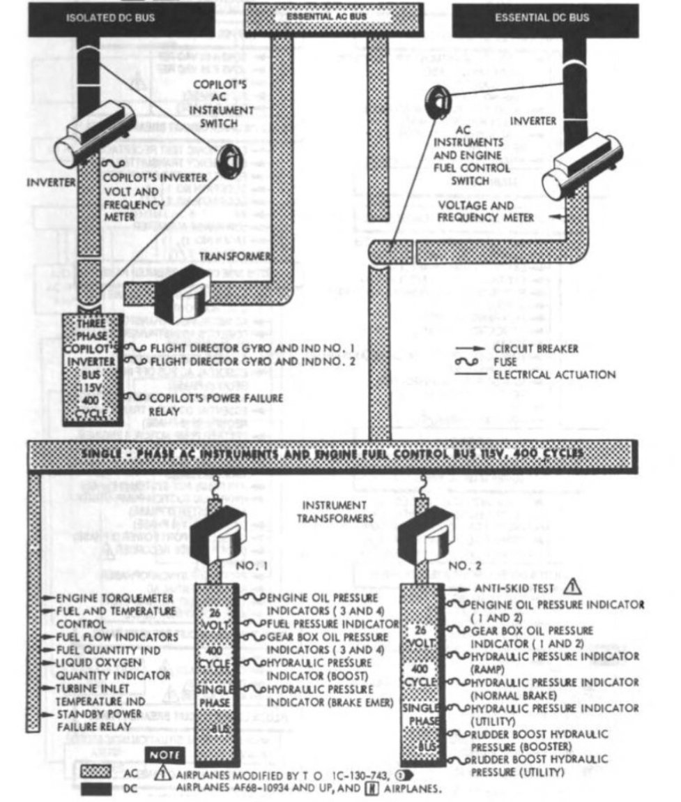
While CBs and fuses essentially "do" the same thing (limit current) the way they do it and the response to overcurrent are different. Generally, Fuses react faster than CBs to overcurrent situations. The component they (CB/Fuse) supply power to determines what type of protection they need. In this case the TQ and TIT Cbs feed 155VAC to power supplies/amplifiers while the fuses provide 26VAC to drive pressure transmitters and gauges without separate internal power supplies.
-
1
-
1
-
-
On 2/25/2020 at 10:53 AM, JON1980 said:
Hi everyone
Are there any differences between fuses and circuit breakers in the secondary AC power supply project? Why design like this?
Thanks
Probably need to add a picture of the schematic you are looking at so we can determine what you are actually looking to understand.
-
1
-
-
While the elevator is sitting on the stop it will bypass pressure (there is an internal bypass) this is discussed in Normal Procedures (engine starting pressures as low as 2550 with elevator on the stop)
In you description is the deflection with both pumps on?
With only one of the pumps on?
With both pumps selected as the sole source of hyd power?
With the elevator on the stop: Start #3 and see what the pressure is at LSGI and then HSGI move the elevator off the stop and see what the pressure does.
Move the rudder and see what the deflection is turn off #3 pump.
Start #4 and repeat.
Let us know what you see
-
20 hours ago, pjvr99 said:
Engine will be cold at 1st start making harder for starter to turn engine. Also FCU will be cold making CIT and CIP bellows
respond differently. 2nd and 3rd start components, gearbox etc. will still be warm and make spin-up easier. Adjusting
TD amp will make little difference as it is only limiting the maximum fuel flow during startup. I see this regularly
on both A15 and D22A engines.
As long as start TIT is between 750 and 830 (780 to 810 desired) and start time is between 39 and 61
seconds (GTC/APU start), there is nothing to be concerned about.
What pjvr99 said...
-
The only explanation I can offer is the No 1 Blade is the reference blade based on the location of the pulse generator therefor it is a know location from which a measurement/ adjustment of relative position can be made during operation.
-
2 hours ago, munirabbasi said:
NATOPS1
Anti-skid Control Box PCB A2 was burnt out what is reason behind it?
Do not test ant-skid during while aircraft is taxing (IC-130B-1 caution) if the testing is carried out during aircraft taxing what happen with the system.
Munir Abbasi
Home of Hercules
As you know anytime a CB or fuse does its job (pop or burn) the amperage through it has exceeded the ratting and you should look for a shorted wire or defective component.
Below the anti-skid arming speed (Taxi speeds) the aircraft will allow for testing. Most serious of the possible issues is the momentary loss of brakes as the control box senses and then losses the "test voltage" (that simulates wheel rotation and skid) which results in the control valvbes porting brake pressure to return "effectly releasing the brakes in response to the detected skid".
The second issue would be the conflicting 400Hz "power input" that is used for testing the system and the "Wheel rotation power" developed and sent to the control box by the wheel transducers.
If the wheels are turning the wheel transducers are sending a "speed signal" to the control box it is just not "fast or hi enough" to be used and the introduction of the test signal will/could cause any number of issues like erroneous light displays which is mentioned in the -1 or the misinterpretation of the dual wheel speed inputs (test and wheel transducers) resulting in loss of brakes or maybe even a burnt/popped CB as the control box tries to determine what to do...
-
On 12/25/2019 at 8:59 PM, Shola said:
Thank you all, particularly NATOPS1, for your assistance. The problem has been rectified. We started by ensuring that there was no known short in the electrical lines. Thereafter, we replaced the voltage regulator, generator control panel and, most importantly, the #2 contractor. We carried out engine ground run and there was no more burning of the voltage regulator.
SUCCESS!!
-
16 hours ago, munirabbasi said:
Optimum angular relationship shown in diagram master of No #2 or No#3 with respect other slave with NO # 3 blade AT 12 O clock
Unless I misunderstand, the No 1 Blade is shown at 12 O'clock for both the No 2 and No 3 Master prop selected.
16 hours ago, munirabbasi said:why the phase angle relation of No#3 Blade only with master. Any dynamic reason opposite blade of No.#1 to No #3
Can you rephrase your questions? Not sure what you are asking as it seems there are many different questions.
"why the phase angle relation of No#3 Blade only with master."
"Any dynamic reason opposite blade of No.#1 to No #3"
-
Which engine generator are we discussing? Other generators on line before starting this one? Does it "burn" at low speed ground idle or at high speed ground idle?
-
First (which it sounds like you already have) make sure Gen and VR are from the same manufacture and compatible, been a long time but different manufactures have different excitation voltage requirements.
-
Books say it cracks at 3300, full open at 3500 and resets at 3100
-
good work!
-
On 12/5/2019 at 4:11 AM, munirabbasi said:
Hello Hydraulic expertise
AT 60 KN brake release during landing ,The operation checked o ground found normal with tester .Wiring of the system was checked satisfactory .Anti-skid control box replaced and sufficient hydraulic bleeding carried out but defected was repeated.
Munir Abbasi
When you say release do you mean AS the crew is pushing on them? Are they full anti-skid braking or normal to light pressure?
-
On 11/24/2019 at 6:48 AM, AussieHercMaintainer said:
Condition is only happening on a steep decent into a higher altitude airport.
Are the flaps being moved at higher airspeeds (IE: 220KIAS for 10%) or are they slowing to 180 and then moving the flaps to 50%?
 Might be a "quick access" panel someone made to get to the ext power/ freq sense relays. Think that is the right panel... SHOULD BE a BIG RED WARNING sticker there toooooo
3505786-1 air turbine starter
in C-130 Technical
Posted
I agree it should not actually be able to engage but the fact it will be "disengaged" does not mean it will not try to engage as it spins up nor that it will spin up to max rotation speed "unladen" and disintegrate causing damage to the engine.