

munirabbasi
-
Posts
381 -
Joined
-
Last visited
-
Days Won
5
Content Type
Profiles
Forums
Store
Gallery
Downloads
Calendar
C-130 Hercules News
Posts posted by munirabbasi
-
-
9 hours ago, Cho said:
Hi
i wanna ask you about the elevator and its relation with the elevator trim tab, when the nose is Down what's the position of elevator and the trim tab?
Trim tab up elevator Down Nose Down.
Best regards
Munir Abbasi
-
4 hours ago, Farhanz said:
will the T plunger will broken once initiated sir? i meant, the hardened steel plunger was found released. however, i did not know where is the exact location of the fusible plug mentioned in my manual. how is it melt and how is it released the plunger by melting the fusible plug??
Please Contact me my E.mail address muhammadmunir332@gmail.com
Best regards
Munir Abbasi
-
5 hours ago, hithroel said:
Hi Folks,
I'm currently planning a new module, the fuel-management. Can anybody help me with the question why the fuel management panel of a J-model (the one with the rotary switches and digital readouts) has only one tank selector? What is that rotary switch controlling? I dont find anything about a fuel selector in the public available schemata.
Regards
Thomas
If anybody ist interested in the current status of my sim: https://c130-sim.weebly.com/
Contact Ummar Hayyat on
Omar Hayat Khan omarhk
-
6 hours ago, Farhanz said:
Advise, sir. Did u know how or what are the things that cam cause the plunger mushroom to break as its natural working operation shouldnt be like that sir.
Please let me know actual defect during flight . This was not alarm of system during flight which has been mentioned by you sir on forum. It seem to malpractice of flight engineer
CAUTION Holding GEN DISC TEST switch for an excessive amount of time will fire disconnect(24-20-06)
mechanism.Best regards
Munir Abbasi
-
19 hours ago, Farhanz said:
Hye guys. I really need help. I had an experienced on this issue. Mine generator disc indicator on the overhead panel not illuminate during test. Before test, my aircraft do experience generator out light and failed bearing light illuminate in flight. Pilot tried to disconnect the generator with the gearbox using generator disconnect system, however the indivator didnt illuminate and it forced pilot to shutdown #3 engine to avoid catastrophic mechanical failure. On the rectification after the flight, it found that the generator had broken with shaft do also broken. From my understanding, failed bearing light is due to mechanicle failure or maybe due to the broken of the generator. However, im still confuse that my gen disc indicator not illuminate during test after replacing generator, VR and GCP. When further rectification on gen disc assy, i did found spring loaded hardened pluger of gen disc assy was broken. Once replacing the plunger, gen disc test light illuminate. Can someone please explain to me?
Dear sir you have done rectification/ FI totally wrong. test system of DISC system of light is used to check out all disc circuity of plunger
When GEN is Disconnected from RGB it has been fired.The OUT light of GEN illuminated due to its rpm drop. But DISC light was failed to illuminate reason Plunger disc micro SW was obstructed due to malfunction of SW or plunger mushroom
Munir Abbasi
-
On 3/25/2021 at 9:25 AM, costy21 said:
Thank you for your reply!
Do you have any ideea what's the cost for a Lockheed drawing and if they can release (for a fee) a single drawing?
Contact to Lockheed customer support representative
hercules.support@lmco.com
Munir Abbasi
-
On 3/23/2021 at 9:35 AM, costy21 said:
Hello Herc masters!
I"ll be thankfull if you could provide me Drawing no. 3305083 Rev. A, necessary for applying SB 82-790 CW Widepread Fatigue Damage Inspections and TCTO 1C-130-1908.
Thank you very much!Munir Abbasi
-
On 3/23/2021 at 9:35 AM, costy21 said:
Hello Herc masters!
I"ll be thankfull if you could provide me Drawing no. 3305083 Rev. A, necessary for applying SB 82-790 CW Widepread Fatigue Damage Inspections and TCTO 1C-130-1908.
Thank you very much!This document contains technical data whose export is restricted by the Arms Export
Control Act (Title 22, U.S.C., Sec 2751, et seq.) or the Export Administration Act of 1979, as amended, Title
50, U.S.C., App. 2401 et seq. Violations of these export laws are subject to severe criminal penalties.
Disseminate in accordance with provisions of DoD Directive 5230.Munir Abbasi
-
20 hours ago, mmrana903 said:
Reasons of burning out of Heading Coupler #1. Two Heading Couplers got burned in #1 position, one after another, while voltage and wiring found okay.
Check grounding of system
Munir Abbasi
-
4 hours ago, Check Team FR said:
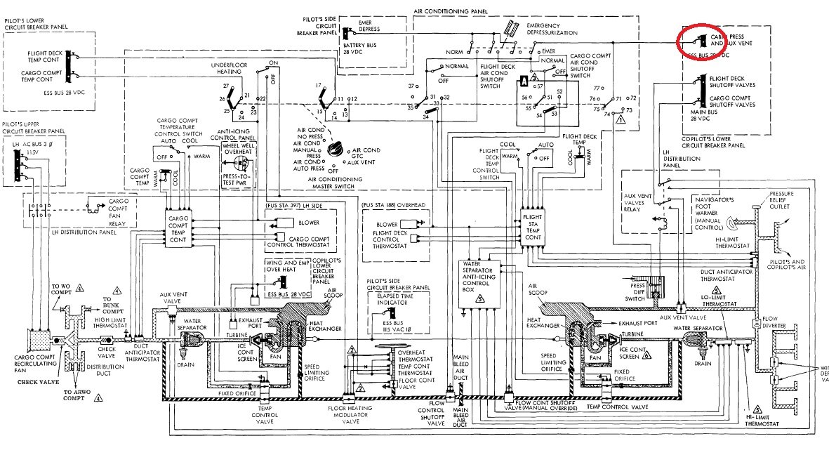
At the end of the flight, when the aircraft is reconditioned: When I set the Air conditioning Master Switch to OFF or AUX VENT, the breaker cabin press and AUX Vent triggers after 2 seconds. On positions NO PRESS, PRESS MAN or AUTO PRESS, the breaker does not trip ... I have a doubt about a piece of equipment but I would like to have your avionics opinion. Thank you
Check wiring of air-conditioning system O IC-130B-13 Safety valve , with disconnect of Outflow valve and aux vent systems connectors one by one
see attach schematic
Munir Abbasi

-
13 hours ago, Leakybirds said:
Question for you guys. I have a c130h transferring fluid from the aux system to the utility system. Ive replaced the Ground test valve and the utility system accumulator (which had a leak internally). Neither of those parts solved it and it is still happening. Thoughts on where to go from here?
Please See S NEWV9N2.pdf
Munir Abbasi
-
19 hours ago, Fargusmcg said:
Hello all,
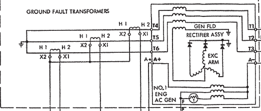
Working on a KC-130T-30 and having an issue with the #2 and #4 generators holding a load. Replaced multiple components: #4 gen contactor, one of the bus tie contactors, #2/4 GCP, #4 voltage regulator. Generators will power on and give good freqs and voltages but when switched to on will not carry essential bus or a heavy load. Occasionally we can get either to pick up a bus or remove applied loads and slowly turn items on till the gen out light illuminates and freq and volts are zero. Have verified wire continuity and voltages while gen is operating normally everything checks good. When gen is in a failed state the normal voltage at the voltage regulator pin F should read 5~13 volts DC will read 100+VDC. All systems function normally with gen #1, #3 and APU supplying power. Any insight would be greatly appreciated.
Have you check the load of the generator before GEN OUT light illuminated. it probably defect of GEN GFT, installed in reverse polarity . Checked all six GFT polarity ie H1 and H2 IAW TO IC-130B-2-13
Muniir Abbasi
Home of Hercules Pakistan
-
 1
1
-
-
On 1/30/2021 at 12:30 AM, NATOPS1 said:
ALSO FYI; The flight station mounted bleed air gauge reads 6 PSI lower than actual pressure. Add 6 to the indicated pressure for actual pressure being supplied.
Thanks
Munir Abbasi
-
On 1/17/2021 at 4:11 AM, AMPTestFE said:
And remember, on those older E models, you have the two urinal drain bleeds, in addition to the jet pump on the outflow valve and the safety valve constant flow points.
Thanks
Munir Abbasi
-
On 1/30/2021 at 12:45 AM, NATOPS1 said:
Question #1: No idea on GPM @ 3000 rpm between 6 and 12 is all I got on that...
Question #2: Just assume that aircraft hydraulic utility system ,when No 1 EDP pressure is 3000 psi and No.2 EDP pump pressure 3100 psi how the pressure act passes thru passage of single pipe after isolation check valves ?
The 3000 PSI pump will be at zero flow because the pump compensator (set at 3000) is satisfied with the pressure. The isolation check valve for this pump will be closed due to the 3100PSI being applied to the check valve preventing it from opening.
The 3100 PSI output pump (compensator is set incorrectly) will displace fluid to maintain 3100 PSI, it's isolation check valve will be open and the system pressure gauges will read 3100.
As hydraulics are used the pressure will drop and the 3000 PSI pump will be allowed to help out but only until the 3100 PSI pump builds its pressure back to 3100, then the 3000 pump will again go to zero flow condition.
Thanks
Munir Abbasi
-
8 hours ago, tinyclark said:
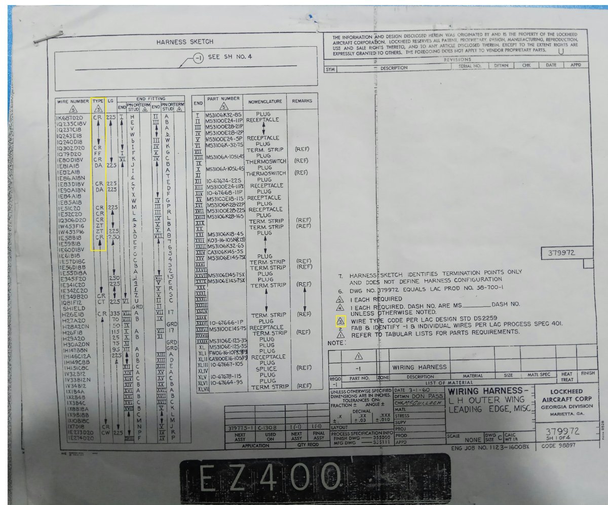
There are way too many LAC processes to remember that much. Also, some wiring was replaced by newer designs. The 1-!A-14 has the story on aircraft wiring.
Thanks
Munir Abbasi
Home of Hercules Pakistan
-
On 1/12/2021 at 5:43 AM, tinyclark said:
You will have to contact Lockheed. I used to have access to those LAC processes when I was working.
Sir Gary your excellent engineer/technician of electrical wiring and hope you will collect the previous best memory and reply.
Munir Abbasi
Home of Hercules Pakistan
-
Hello Avionic Wiring Expertise!
Kindly see yellow marked column of image and explain with technical reference
Best Regards
Munir Abbasi
Home of Hercules Pakistan
-
Excellent spirit and pay of attention
Munir Abbasi
-
7 hours ago, hehe said:
The Ejected pressure from the engine should never indicate exactly in the flight deck for quite a few reasons.
1. Pressure drops across distance. In order to get 125 psi in the flight deck, the engine would need to be making 150-ish psi at the engine (just an estimate). Pressure drops across distance because flow and volume is required to get that pressure across a distance.
2. The system has allowable and normal leaks. Every valve in the system is bleeding off or leaking a small amount. Some are calibrated to leak a certain amount and others just leak as a result of their design. Very few pneumatic systems are perfectly leak proof. For example, if you have 20 valves in a system and they are all leaking small amounts of air, your 125 psi becomes more like 70 after the bleed offs. This is why the system has a bleed down time. The drop from 30 to 15 psi in 22 seconds or more is a indication a satisfactory level of "normal" leakage. If there were no leaks in the system at all, your bleed air pressure would never drop.
3. Almost all systems are like this. Hydraulics, fuel, electrical, oxygen, etc. The system is designed to provide a higher amount than is required so that it can "bleed off" some for normal system losses and still provide a set amount.
Hope that helps.
Tanks
Munir Abbasi
Home of Hercules Pakistan
-
10 hours ago, pjvr99 said:
at sea level, a 0/low time compressor will make 80 to 85psi at normal ground idle. This increases
as throttle is advanced towards take off an TIT increases. The highest I have ever seen was 130psi.
This was a 0 time engine where the CDP fell in "high" zone of the compressor graph. Compressor
performance is based on OAT and pressure altitude.
Thanks for excellent response .let me rephrase my query regarding Engine bleed output pressure at Engines throttle higher setting. normally the pressure is indicated in flight deck bleed manifold Gage approximately 70 to 80 PSIG where one engine output pressure is 125 PSIG at 155 ppm . Question arise in my mind that one engine bleed output is metered 125psig but all four engines operating at higher throttles setting is droped to 70 to 80 psig when both air -conditioning are ruing condition with flow rate of 70 ppm and 30 ppm.
Best regards
Munir Abbasi
Home of Hercules Pakistan
-
Hello T56A -15 power plant Pneumatic Expertise
T56A-15 (C-130 E model) engine can provide approximately 155 pounds of air flow per minute at 635F and 125 pounds per square inch of gauge pressure. Bleed manifold pressure gauge is mounted in F/deck (direct gauge) display approximately 70 PSIG .where remaining pressure of the engine flow?
Best Regards
Munir Abbasi
Home of Hercules Pakistan
-
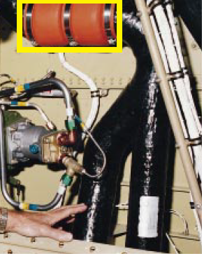
Hello Pneumatic expertise Identify and purpose of mark image

Munir Abbasi
Home of hercules Pakistan
-
13 hours ago, Kaydee said:
whenever i am running the APU, the fire warning light on both master warning light and the APU T-handle light come up and remain steady once i put ON the air condition. however, if the air condition is not running, the operation of the APU remains normal. i have tried to check for bleed leaks from he APU to the manifold and no leak was found. pls i need urgent help on what next to look up to pls
There no APU Fire alarm system is connected to air-conditioning system .Problem is APU pneumatic ducting. It might be exhaust duct partial became rapture.
Best Regards
Munir Abbasi
Home of Hercules Pakistan
Generator Disconnect light not illuminated during test
in C-130 Technical
Posted
Excellent JPG Picture of GEN DISC SYSTEM SCHEMATIC
Besr Regards
Munir Abbasu