


hehe
-
Posts
247 -
Joined
-
Last visited
-
Days Won
8
Content Type
Profiles
Forums
Store
Gallery
Downloads
Calendar
C-130 Hercules News
Posts posted by hehe
-
-
1 hour ago, JPWILLYS said:
Thanks Hehe. I don't know DTIC ? It's a data base?
The picture of FLIR is from google, just to illustrate my question.
DTIC is where all Air Force Research and test reports get databased. Ill do a search and see what I can find. Is there a certain model of FLIR that you are looking at?
-
12 hours ago, JPWILLYS said:
Thank's for the answers.
I'am working on a similar project and the FLIR internal heating capacity does not guarantee deicing. Consequently I inquire about this aspect knowing that the lower pitots are behind.
I don't know that it was ever designed to completely de-ice. I believe the heating is only there to prevent the image from being obstructed. There are plenty of models that have no de-ice or heaters built in and they work fine. I believe the original picture you posted is a model without heating.
Do you have access to DTIC? I find a lot of good reports on that site and it might be a good place to look for this.
-
9 hours ago, DC10FE said:
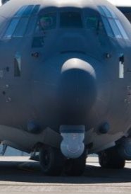
It's been 51 years since I've been on the B-model, but I don't think that's a B-model with the Rosemount pitot system and the LOX service door. Just picking a nit here. Nice pic, though.
Don R.
It looks like an N-model, def not a B-model for sure. Maybe he meant nice "P-model"?
-
6 hours ago, JPWILLYS said:
Thanks a lot for your answer "Hehe".
My concern is with potential significant ice accumulation under severe icing conditions and potential flow "disruptions" in front of lower pitots tubes (static pressure error ?) with AoA for exemple.
I have worked many C-130s with FLIR and never seen accumulated ice on them, especially not enough that would alter airflow.
Of all the designs, the one you pictured is one of the smaller FLIR designs. Have you seen the MX-25? Huge FLIR, and they are operating that on the C-130J which has dual pitots on both sides of aircraft.
Is there a problem you are seeing that you think is caused by ice build-up on FLIR?

-
I am unaware of any icing limitations, I would have to dig through ops manuals to see but i can say that some models have window heaters that prevent ice build-up that could block the camera.
-
21 hours ago, C130ron said:
Check the Nose Wheel Steering Actuator rod ends for play. The bearing is press fit into the rod end, if you pull the bolts out, and the bearing falls out of the rod end, the actuator is bad. Both actuators usually go bad at the same time. There are 2 modes for the steering control valve, shimmy dampening and steering. In shimmy dampening mode a small amount of fluid is ported to both actuators for a shock absorbing effect. if the tires, bearings, Control Arm Bushings and cable tension is good... only then change the steering control valve.
You got quite a bit wrong here.
1. The rod end bearing are slip fit. If they fall out its just because the adhesive has failed. Those bearings are literally glued in. I have rebuilt/overhauled hundreds of them, the bearings slide right in and get glued in place, I have never seen one become loose enough that it would cause a shimmy, even if the glue fails.
2. No fluid is ported during shimmy dampening. The control valve goes to neutral and the sprung piston accumulator in the control vave takes the shock from the actuators to prevent abrubt movements. Fluid is ported during steering mode only.
-
The only thing I can think that relates that ECBU #12 to this problem would be the tail section cannon plug disconnects. Similar to what you found near booster, there are huge cannon plug disconnects aft of the #12 ECBU. They are where the tail section electrical system ties into the fuselage. Check those. You might have moved some wires into a good position during that ECBU swap.
-
Five total? Same aircraft? Same engine? or just five across your fleet?
mounting bolts or bolts on generator?
-
Yea I still think its database to MFCD. shoot 1553 to MFCD
-
Meant to reply to you. I cant send you these to another country. You need to contact your FMS representative or reach out through TCG if you cant find what you need. If you were US, I could send them to you
-
Sent you a PM.
-
Are you getting an ADS Airdrop Light on the ADS panel in flightdeck when ramp/door are both full open at ADS position?
If so, it is the wiring that gives that signal to the MFCD.
If you dont get ADS light in flightdeck, it is the ramp/ads arm switches.
-
Airmen Third Class
-
Find someone with PDM gateway access. if you have a military email address, I can send them to you.
-
I am looking for information about the first C-130 delivery to USAF at Ardmore AFB in 1955.
I believe I have a resin model of the C-130A that was presented to TAC commander by Lockheed during the aircraft delivery ceremony.
It is 100% dated to Ardmore AFB and sometime between 1955 and 1956.
Can anyone help out?
-
I like to think aircrew did nothing wrong but yea its possible especially aft wheel
-
Assuming you performed fault isolation and normal operational checks,
Check back pressure of brake system (should be under 70 PSI at each wheel, if one brake reads 10 psi or more higher, look farther) , check minimum brake pressure (should be over 1700 psi and max around 2030 and should be equal between left and right under same pedal pressure), check electrical grounds for anti-skid control valves (ensure they are tight and not corroded), check anti-skid control valve filters (if dirty, replace), check brakes for ability to return (watch pressure plate return after pressure release, should return equally), check tranducers for smooth operation and check voltage output with drill.
If you find nothing, replace parts in this order. 1. anti-skid control box. 2. anti-skid control valve. 3. transducer
Without being there and being able to look at it, this is about best I can offer. Tons of things that could cause this but most involve electrical signal between transducer/box/valve.
-
 1
1
-
-
thats a fleet lol. dont get so caught up on it. that article is trash anyway. no real info there
-
-
International Air Response flies some very regularly. Most A models flying are confused as L-100 because if their civilian use. I can get you tail numbers later
-
i get your point but.....There are still quite a few A-models flying.
-
-
I have never heard of a time limit. which indication is "slow" to stabilize?
-
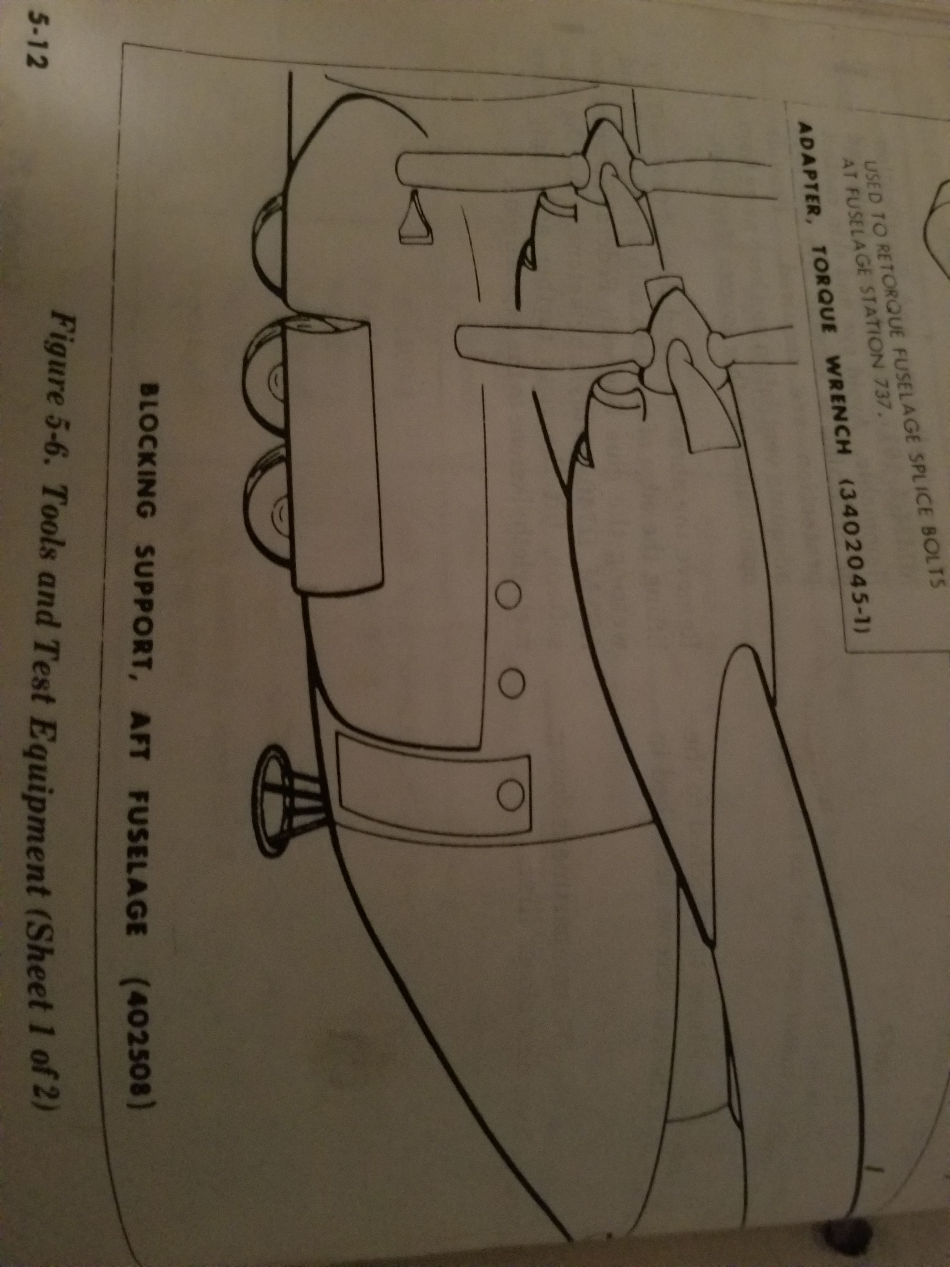
yea thats the support Im talking about.....it is the milk stool lol.
look at the photo, then do a google image search for milk stool and tell me where the name "milk stool" came from........
EDP
in C-130 Technical
Posted
Yes, as long as you have a run around installed for New York Air Brake pump (if installed). There are Lockheed Service News that talk about this.