

munirabbasi
-
Posts
381 -
Joined
-
Last visited
-
Days Won
5
Content Type
Profiles
Forums
Store
Gallery
Downloads
Calendar
C-130 Hercules News
Posts posted by munirabbasi
-
-
Hello Sim Instructor /Engineer!
Any Herks Sim Instructor know that Hercules training simulator sim programming are based on PLC or not. Which manufacture PLC is equiped with sim module. How many bit are installed on this binary program i.e 64 bits or 32 bits.
Best Regards
Munir Abbasi
Home Hercules Pakistan
-
6 minutes ago, Taimoor said:
Its good to know what others are doing as it might pave a way for our modifications as well!
Main Feature of C-130 H Model is upgrading of pneumatic system and GTC & ATM are replaced by APU system
Best Regrads
Munir Abbasi
-
EXCELLENT IDEA
Munir Abbasi
-
Happy Christmas wishes to members of Herks
Munir Abbasi
Home Hercules Pakistan
-
3 hours ago, Kamrul Ahsan said:
Sometimes Generator voltage travels from 120 to 125V, again comes back to 120V after 15-20minutes of flying. It is not fluctuations but slow travelling. Is there anything to worry about? Frequency always remains same, that is 400cps.
Kamrul Ahsan Sahib. Type of GEN brushless or brush type? All ENG GEN? No load condition of GEN Voltage may exceed to 125 V until the voltage is regulated by VR , normally it does not happened.Your defect belong to malfunctioning of VR or Excitation generator poles.check the voltage "A "point (PMG) VR terminal block 1 it should be 108 volts AC (GE GEN) if Bendex type 30 V DC . If westinghouse GEN (Brush type) It has No PMG. than "F" point to A to-A of VR (TB-1) 3.75 to 7.5 Vlots (GE), Bendex 30 Volt. If brush type (Westinghouse) check boost XFMRs are mounted F.S 245.

Best Regards
Munir Abbasi
Home Of Hercules Pakistan
-
6 hours ago, Kamrul Ahsan said:
Sir i was the student of urs in a Type maintenance course in Pakistan.. hope you remember. Sir apart from generator, what else i can check for such kind of failure. Like you said RGB vibration. Though i am not clear how to check the RGB vibration.
Dear Normal large scale vibration is display RPM IND thru tachometer generator. but a device is installed on ENGINE RGB to display vibration of Engine /RGB parameters on Engine digital display unit ie EIDS.
Best Regards
Munir Abbasi
Home of Hercules Pakistan
-
10 hours ago, hehe said:
Here is a C-130 flight manual for reference.
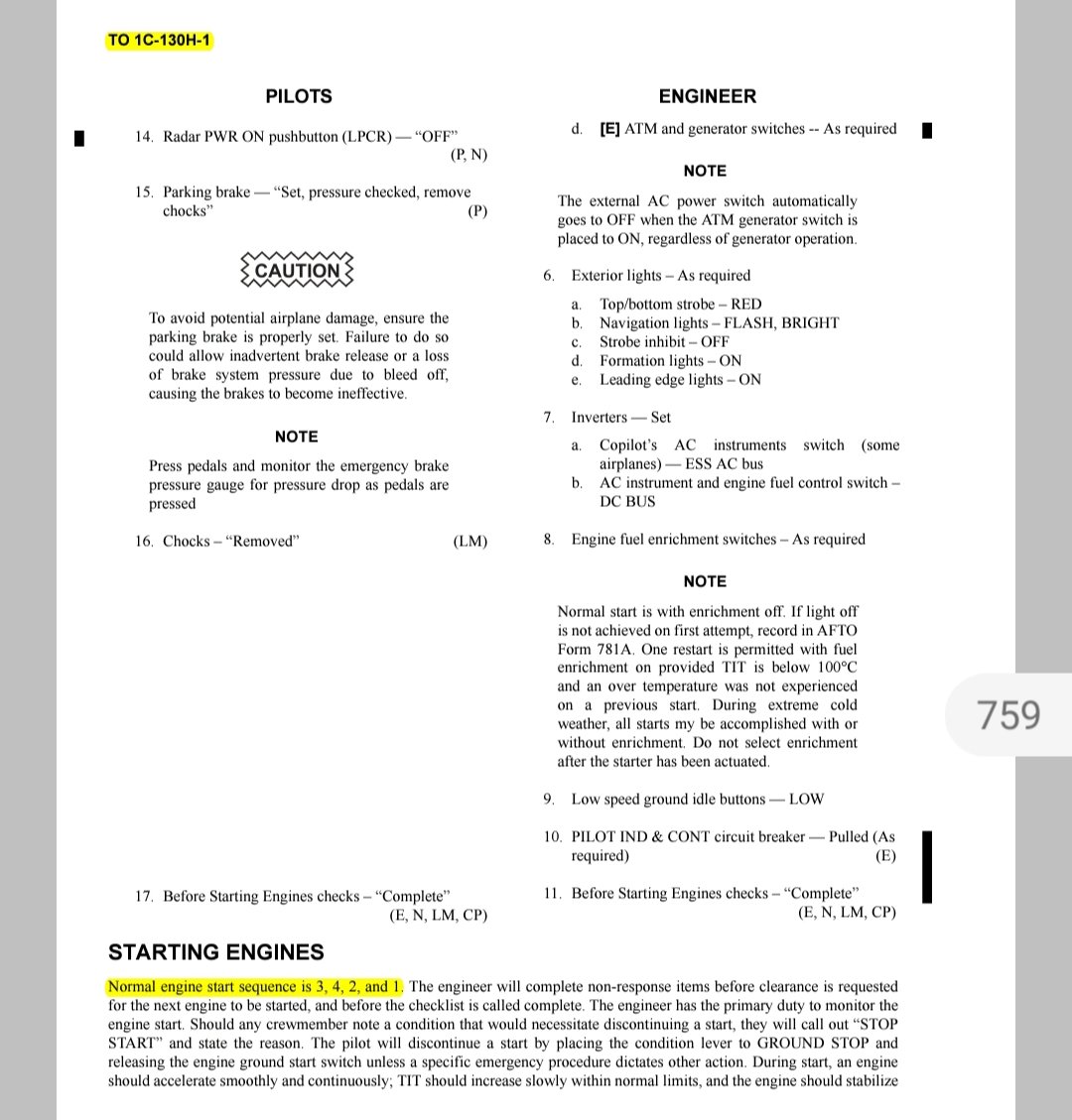
This sequence started on A models because the GTC door had to be manually closed and the engine generators were split between inboard/outboard. So they would start #3 and #4 and then shut down GTC, manually close the door and then start left wing.
Some pubs mention starting engines in a different sequence than 3/4/2/1 to spread the wear and tear on engine starters. The first engine started off of GTC/APU Bleed air will wear faster than the others with engine bleed air because of the higher flow/pressure from the engines.
Generally speaking, if you 100% always start #3 first, data/trends say that you will replace the #3 engine starter before the other engines.
Thanks tremendous response
Is t SAFAR safety regulation by FAA Or USAF safety regulation ,any safety caution reference of TM or FM is available please mention the text
Best Regards
Munir Abbasi
Home of Hercules Pakistan
-
17 hours ago, Kamrul Ahsan said:
Sir what are the reasons and indications available for this type of problem? How to determine RGB vibration? How can i check if some other thing causing failure of generator bearing?
My 30 year experience say. that front bearing housing clearance more/or play between GEN end plate bearing housing and bearing. Change the GEN end plate. all GENs End PLATE should be checked during phase inspection/ISO inspection
2. Greasing must be carried out after three years elapsed time if your using ball bearing of USAF standard.
Best Regards
Munir Abbasi
Home Hercules Pakistan
-
On 12/15/2020 at 9:36 AM, Taimoor said:
Is the modification solely avionics based or does it include other systems of aircraft as well, such as air conditioning system?
Oh!
Munir Abbasi
-
 1
1
-
-
Excellent sharing
Munir Abbasi
Home Hercules Pakistan
-
Hello Herks flyer!
Any body (PL) know that, from where reference is (TM) made to engine ground start sequence 3421 by aircrew for normal flying departure???
Munir Abbasi
Home of Hercules Pakistan
-
3 hours ago, Kamrul Ahsan said:
Hellow friends and brothers
i just wanted to know what are the reasons behind the generator shaft bearing(only front) failure in C-130B ac with T56-A-7B engine.
Due to ENG RGB vibration.install GEN DISC System and Bearing failure system.
Best Regards
Munir Abbasi
Home of Hercules Pakistan
-
4 hours ago, hehe said:
1. I will have to double check but I think the 3k RPM is low speed ground idle and 3.6K RPM is normal ground idle (engine at 100% rpm)
Why would you ever need to figure out the GPM at low speed ground idle? You would never fly at that engine RPM
2. Pressure equals out. If you had 3K and 3.1K you would probably see a little bit above 3K by the time the pressure equalized and got to the pressure transmitter at the utility or booster panels. Pressure drop is roughly 100 psi every 50 feet (not written down anywhere just what I have seen)
Thanks for Marvelous response. Your services for Hercules operators will be remember in godlessnesses wards forever.
Munir Abbasi
Home of Hercules Pakistan
-
Hello Herks Hydra Expertise!
1. It has mentioned Intermediate level maintenance T.O of EDP NYAB at 3000 RPM , flow rate of pump is 6 GPM min, where pump is designed 10 GPM at 3650 RPM . when both the pumps (NYAB) In Aircraft utility system working parallel max flow ie 16.93 pressure drop to 1800 psi. how we can calculate flow rate (GPM) of both NYAB pumps when they are working parallel at 3000 RPM?
2 Just assume that aircraft hydraulic utility system ,when No 1 EDP pressure is 3000 psi and No.2 EDP pump pressure 3100 psi how the pressure act passes thru passage of single pipe after isolation check valves ?
Best Regrads
Munir Abbasi
Home Hercules Pakistan

-
Hello herks structure expertise
If center wing is replaced with the wing of 500HRs EBH Elapsed time What will be EBH of of the aircraft???
Best Regards
Munir Abbasi
Home of hercules Pakistan
-
10 hours ago, hehe said:
Check the simple things
Util reservoir filters (pressure return/case drains and reservoir vemt filter). Something as simple as a wet vent filter can cause enough of a liquid lock that pump would cavitate during large draw such as landing gear movement.
Swap the low pressure switch to booster side. See if it follows the switch to booster side.
Check the landing gear flow regulators. Should be free flow toward motor and regulated away on both up/down lines.
What was the util system pressure drop? Did it drop below or around 1300 psi?
Thanks for immediate response
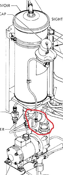
Oh! Flexible hose, mounted bottom of reservoir was found Collapsed
Munir Abbasi
10 hours ago, hehe said: -
9 hours ago, hehe said:
Check the simple things
Util reservoir filters (pressure return/case drains and reservoir vemt filter). Something as simple as a wet vent filter can cause enough of a liquid lock that pump would cavitate during large draw such as landing gear movement.
Swap the low pressure switch to booster side. See if it follows the switch to booster side.
Check the landing gear flow regulators. Should be free flow toward motor and regulated away on both up/down lines.
What was the util system pressure drop? Did it drop below or around 1300 psi?
Thanks for immediate response
Oh! Teflon hose , mounted bottom of utility system reservoir was found kinked
-
3 hours ago, hehe said:
Is this the same aircraft that was having these issues? There was a post about a week ago with similar issues
Previous history of this? Any recent maintenance done?
I wouldn't automatically call it bad if it just flickered. It could be a loose cannon plug on the low press switch and the gear going up shook the wall. It could just be a loose push to test on the warning light.
What has been done to resolve?
No and No previous history of hydraulic defect or maintenance regrading hydraulic system. Low PRESS WX SW connector was checked found SAT . wiring security and circuit checked found SAT . Defect could not duplicate on ground.
Best Regards
Munir Abbasi
Home Hercule4s Pakistan
-
43 minutes ago, Taimoor said:
Defect code was analysed. Problem was with the reversionary relay.
Thanks
Munir Abbasi
-
Hello Herks Hydra Expertise!
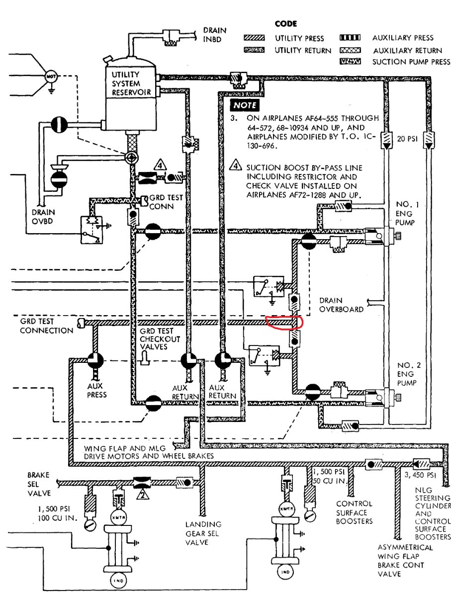
B model aircraft,During Retraction cycle of landing gears with UT system (in-flight) low pressure WX light of UT suction boost pump was Flickered and extinguished when gears were up and locked. Manufacture of Suction pump is able corporation sealed type and without cooling FAN and also without modification (C-130E airplanes AF72-1288 and up and C-13OH airplanes have a suction boost by-pass circuit. The by-pass line contains a restrictor and a check valve that will continuously circulate one GPM of fluid, from the suction boost pump back to the booster system reservoir, to provide a cooler operating boost pump). FE Said operation of LDG were not conducted along with FLAP ops simultaneously. any expert opinion
Munir Abbasi
Home Hercules Pakistan
-
13 hours ago, Taimoor said:
Hello C130 professionals!
In an E Model Hercules, Flight Director Flag (FD flag) came in view on Co Pilot side PFD on ground during normal checks. Against the defect, all associated LRUs were replaced/swapped with serviceable ones. Even the PFD was swapped with pilot side, yet the flag did not disappear. Continuity of wiring was also double checked and was found SAT. No visible issue was observed yet the flag did not disappear. Autopilot engages without any defect and is working fine. Any ideas as to what might cause this or any previous experience, please do share.
Thanks!
Use the built-in
diagnostics to troubleshoot the autopilot/flight directory
system. Record all 6 digits in sequence of both left and
right columns of the diagnostics data. Press and hold any
3 active MSP buttons for 2 seconds. The PFD shall
display the REPORT MODE. Use the APP Pitch Wheel
to select the codes.Munir Abbasi
-
12 hours ago, Taimoor said:
Hello C130 professionals!
In an E Model Hercules, Flight Director Flag (FD flag) came in view on Co Pilot side PFD on ground during normal checks. Against the defect, all associated LRUs were replaced/swapped with serviceable ones. Even the PFD was swapped with pilot side, yet the flag did not disappear. Continuity of wiring was also double checked and was found SAT. No visible issue was observed yet the flag did not disappear. Autopilot engages without any defect and is working fine. Any ideas as to what might cause this or any previous experience, please do share.
Thanks!
Defect is with SUIT modification aircrafts or IAUP aircrafts!
Munir Abbasi
Home Hercules Pakistan
-
2 hours ago, hehe said:
The 1c-130A-6 references you to the 11A18-14-7
Lot of Thanks
Best Regards
Munir Abbasi
Home Hercules Pakistan
-
Hello Fire extinguisher Squib Herks expertise.
Life cycle of C-130B/E model aircraft Squib is not mentioned neither TOs 1C-130H-2-26JG-20-1 nor IC-130B-2-10 and IC-130B-2-7. but life of squib is mentioned in Service news in Vol 18,no1 which is not applicable in our fleet. any T.O which provides guide line for life of squib ,installed on Hercules aircraft. any expert opinion
Munir Abbasi
Home of Hercules Pakistan
-
 1
1
-
Happy Christmas wishes
in C-130 General
Posted